As part of an earlier look at Parting line creation the option to automatically create a split line for all straddle faces was reviewed. However, it is not always certain that the software figures out where these things need to go and of course there are multiple ways to do everything. Split lines can be created manually as well and doing so is rather simple.
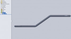
To start out a sketch needs to be created. This can be done on any plane but will be used as the actual splitting line so choosing a plane that is perpendicular to the direction of pull seems most feasible. In the image below the dashed line is a single sketch manually created from midpoint to midpoint of each segment (including arcs instead of lines on filleted faces) which creates essentially the parting line needed. Then the Insert>Cuvres>Split line command allows for face selection as to which faces will be split.
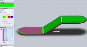
After selecting all of the faces around the edge of the part the parting line tool can be run. Here I selected a single entity and then the handy propagate tool and it automatically created a closed loop around the part.
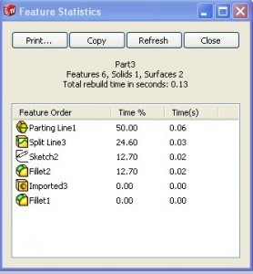
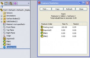
This previous step is similar to the original Parting line creation in another post however there is now no need for the “Split Faces” check box in the feature as the faces have already been split. In cases where things can be done more than one way I usually take a look at the statistics of a rebuilt to figure out if, all else being equal, the shorter feature tree will improve performance. 
Above are the statistics for a manually created split face, that done using the steps in this post. Below are the steps laid out in the earlier pating line post. Oddly, the rebuild time of OTHER features is affected here. Even without the increase in the fillet time the manual Sketch2/Split Line3/Parting Line1 combo above is still a more resource intensive route than the Parting Line2 automated option.
This is just a sample of a quick way to manually split a face. The Insert>Curve>Split face tool however comes into play in applications other than mold tools though. The ability to split out a face provides an option for changing displays of faces, creating text, altering surfaces (CSWP Surface Exam is next after weldments for me).
To look more into working with mold tools check the CSWP Mold Tools review.

COOL! Nice Tutorial