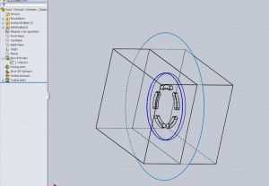
So after reviewing the core and tooling split options, what happens when the resultant mold can not be created or machined easily. There are times when sectioning out a mold even more will make it easier to fabricate or more durable. For example, if molding a rough material that is known to wear away steel over time (such as a high percentage glass filled nylon) it may be desirable to make the smallest features of the mold out of a more durable material. Though there is no reason to steel harden a whole mold base or even a full insert a feature with a tight tolerance may require plating of hardening to ensure it will withstand the life cycle.
Here the “core” feature can be used. Instead of cutting away material and reading it, linking geometry, or creating thin cuts, it is possible to simply outline the portion of the mold that needs to be broken out and let the software create another body. This can eliminate frustrating in mating, sizing, and generally getting complicated with something that is easy to define in lay-mans terms. “I want this section to be separated”.
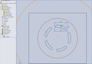
Here I have already creating mold halves using the tooling split. Now by selecting the core tool I am prompted to choose a plane to sketch on.
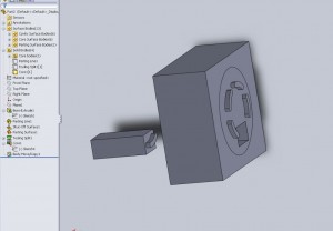
I’ve outline a single section that may be used as a core. Here it is one of the slot cutouts on the sample test “puck” part. Now this mold has no apparent reason to use a core though it works for showing the example. I choose my direction of the core and a few other properties in the feature tree and voila! The software went ahead and created a new component. The picture below I used a “insert>feature>move/copy body” to show what the resultant core looks like if I move it out of the base.
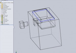
This same process can also be used to create cores that are not in the direction of pull. This allows the ease in creating a side core for undercuts. Side cores can be connected to slides (DME catalog for examples) to create all sorts of crazy geometry.
