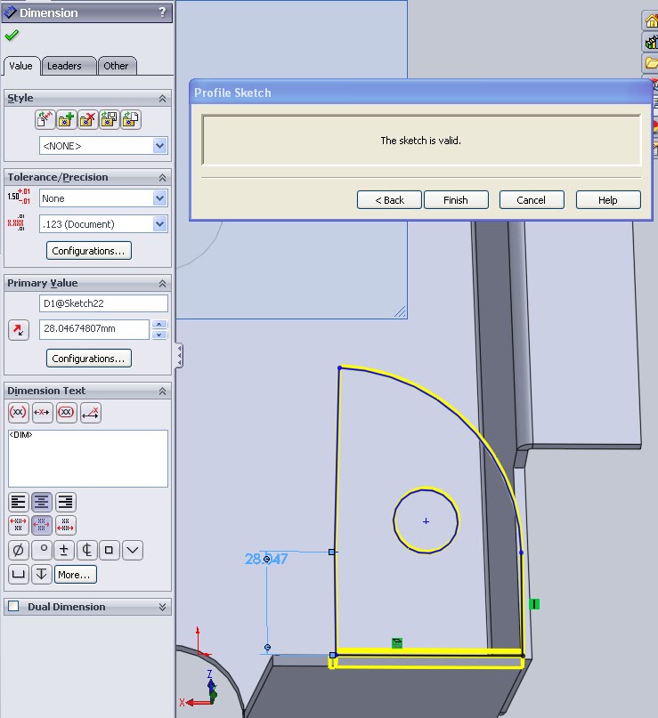
A miter flange is another one of the simple features used in sheet metal modeling. A miter is a joint in wood working or sheet metal and refers primarily to how a corner will match. This is shown right away in the icon used:![]() As with most solidworks features though it can be used for more than one thing. In this case a miter flange can function as an edge flange if only one edge is selected, the difference here is the sketch that governs the resultant flange.
As with most solidworks features though it can be used for more than one thing. In this case a miter flange can function as an edge flange if only one edge is selected, the difference here is the sketch that governs the resultant flange.

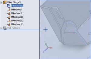
For a miter flange the sketch defines the profile of the flange. This allows curves to be captured within the base sketch. There are also a few differences in the feature manager, mainly the presence of the “Edit Flange Profile”. To edit a miter profile sketch expand the feature tree to access the sketch. As you can see from the image this flange actually contains multiple bends as each segment of the profile sketch gets it’s own feature. It is interesting to not however that these edges all function under their parent. That is, if one of the child bends is suppressed nothing happens, however if the parent is supressed all child features are as well.

So far the first few study sections for the CSWP-Sheet Metal have been fairly easy. I’m expecting the exam to be similar to the CSWP where these basic features defien most of the geometry of the parts and having a solid grasp on them sets you up for success. Still more to study though, for a full list of my review see the base post back at CSWP Sheetmetal.
