 Starting my Mold Tools design review it seems just heading down the list of tools is the best route, so we’re starting with the analysis tools.
When designing for molding one of the first things that should be considered is how the part will be drafted, so it makes sense draft analysis is at the top. I say this not because of the issues I’ve seen with parts sticking in molds, but rather due to the hours spent recreating a part from scratch to capture design intent and fit while also providing the needed draft. Even rather simple parts, when draft is not considered intitially, can become a nightmare to recreate. This is especially true if that part is designed in context of an assembly.
I’ll have another post on Mold design and drafting in the future but for now I’m looking at the draft analysis tool. This is also important because it comes up on the sample exam so it is perfectly acceptable to assume at least 10-20% of the 80% passing grade can be gathered from mastering this tool.
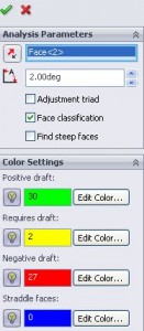
Clicking the draft tool button brings up the feature manager, this can also be navigated to by selecting a parting line tool and then clicking “Draft Analysis”, but using the draft analysis button brings up a different set of options and is the one that should generally be used. The “parting line” draft analysis is more of a last check before creating the parting line. Either way you’ll have to pick a face/plane for direction of pull. When adhering to good modeling principles this should be one of the major axis (Front/Right/Top) planes.

The input here is for the minimum draft (2 in this image) of what is considered positive draft. This angle is the angle crated between the direction of pull and a face. Thus for the actual face selected the angle will be 90 (because the direction of pull is perpendicular to the selected face).
Changing the value will change the display in realtime, so you can actually tell how much draft is on a face as you pass it. If the angle is EQUAL to the draft angle it will appear as positive draft. The verbiage of this is more clear in the “needs draft” field. This real time change also comes into play with the “Adjustment triad”. When selected a triad appears that denotes the direction of pull. Dragging it around will change face colors and can give a sense of what a better parting line may be.
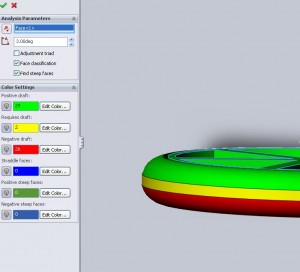
Straddle faces are curved surfaces that include which are both positive AND negative draft. Basically these are faces that will need either a split line or a side pull to create them. A flat surface can NOT be a split plane. Here again having an idea ahead of time as to what the parting line will be can help so that a part can be modeled with mirrors fillets etc that create multiple fillets rather than revolves and sweeps.
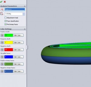
Steep faces are faces that are ONLY positive or ONLY negative but have some portions that are below the threshold of draft angle and others that are fine. This can happen a lot on edges of parts near a parting line where a curved face turns curves until tangent to the direction of pull.


Fixes these faces is not always necessary from a draft perspective as the section that does not satisfy the draft angle may not be a significant portion of the face. Sometimes however these portions will be flattened out to satisfy tolerances. Here if there is a tight tolerance on the total diameter any slight mismatch may cause the part to fail inspection, by simply eliminating the completely round edge these issues can be avoided, this fix is also done for other reasons.
When the “steep faces” check box is cleared these faces are noted as either positive or negative. I have been able to get a steep face to appear under “requires draft” but my draft angles were so enormous (85deg) as to not cause too much concern. Although this could cause some minor issues for the test (and I believe it won’t because of the finite nature of the answer) there is no real world situation where I can see this little detail becoming and issue. If someone disagrees I would be very interested to hear why.
The last issue to note here is the face count. It appears from the sample exam that the main “test” of draft analysis is the ability to pick the right face and then COUNT the number of faces that are positive or negative or require draft. Counting of course is not necessary as the number of faces that satisfy each category is listed in the feature manger.
Look for even study material on the CSWP Mold Tools exam.

Hi Chris,
I need a free or at least cheap tool that does this draft analysis. I want to be sure that my part will be corretly ejected from my mould.
Can you advice me please?
Thx,
Laurent.
This comment has been removed by a blog administrator.